For Loops
A For Loop, shown as follows, executes a subdiagram a set number of times.
The value in the count terminal (an input terminal), shown as follows, indicates how many times to repeat the subdiagram.
Set the count explicitly by wiring a value from outside the loop to the left or top side of the count terminal, or
set the count implicitly with auto-indexing.
The iteration terminal (an output terminal), shown as follows, contains the number of completed iterations.
The iteration count always starts at zero. During the first iteration, the iteration terminal returns 0.
Both the count and iteration terminals are 32-bit signed integers. If you wire a floating-point number to the count terminal, LabVIEW rounds it and coerces it to within range. If you wire 0 or a negative number to the count terminal, the loop does not execute and the outputs contain the default data for that data type.
Add
shift registers to the For Loop to pass data from the current iteration to the next iteration.
While Loops
Similar to a Do Loop or a Repeat-Until Loop in text-based programming languages, a While Loop, shown as follows, executes a subdiagram until a condition occurs.
The While Loop executes the subdiagram until the conditional terminal, an input terminal, receives a specific Boolean value. The default behavior and appearance of the conditional terminal is Stop if True, shown as follows.
When a conditional terminal is Stop if True, the While Loop executes its subdiagram until the conditional terminal receives a TRUE value. You can change the behavior and appearance of the conditional terminal by right-clicking the terminal or the border of the While Loop and selecting Continue if True, shown as follows, from the shortcut menu.
When a conditional terminal is Continue if True, the While Loop executes its subdiagram until the conditional terminal receives a FALSE value. You also can use the Operating tool to click the conditional terminal to change the condition.
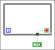
If you place the terminal of the Boolean control outside the While Loop, as shown in the following figure, and the control is set to FALSE if the conditional terminal is Stop if True when the loop starts, you cause an infinite loop. You also cause an infinite loop if the control outside the loop is set to TRUE and the conditional terminal is Continue if True.
Changing the value of the control does not stop the infinite loop because the value is only read once, before the loop starts. To stop an infinite loop, you must abort the VI by clicking the Abort Execution button on the toolbar.
You also can perform basic
error handling using the conditional terminal of a While Loop. When you wire an error cluster to the conditional terminal, only the TRUE or FALSE value of the
status parameter of the error cluster passes to the terminal. Also, the
Stop if True and
Continue if True shortcut menu items change to
Stop if Error and
Continue while Error.
The iteration terminal (an output terminal), shown as follows, contains the number of completed iterations.
The iteration count always starts at zero. During the first iteration, the iteration terminal returns 0.


